
Introduction
In the fields of industrial fluid circulation, new energy thermal management, precision equipment cooling and intelligent liquid supply, BLDC pump and BLDC water pump have become indispensable core fluid transmission components. They replace traditional brushed water pumps with outstanding performance advantages that we have verified in years of engineering applications.
This definitive engineering guide starts directly from practical application demands. We systematically explain the core definition, working principle, internal structure, classification standards, basic functions and performance advantages of BLDC pumps and BLDC water pumps. We also provide in-depth comparison with traditional brushed pumps, and sort out real application scenarios, applicable power supplies, speed control methods, service life and maintenance rules.
In addition, this guide summarizes common selection misunderstandings, scientific selection criteria, practical maintenance and troubleshooting skills, professional flow and head test methods, standard usage steps and operation precautions. All content comes from engineering practice data and field application experience, without empty marketing rhetoric. It provides professional and actionable technical reference for mechanical engineers, thermal design engineers, equipment selectors and maintenance technicians.
Table of Contents
What Is a BLDC Pump?
A BLDC pump (Brushless Direct Current pump), also widely known as brushless dc pump, is a precision mechatronic fluid transmission device driven by a permanent magnet brushless DC motor. It integrates electronic commutation, hydraulic optimization and precision sealing technologies. Unlike traditional brushed DC pumps that rely on physical carbon brush-commutator contact, the BLDC pump uses non-contact electronic commutation controlled by a dedicated driver chip, completely eliminating mechanical friction and wear during operation.
As a high-efficiency fluid component, it converts DC electric energy into stable mechanical rotational energy, driving the built-in impeller to generate pressure difference and realize liquid circulation, pressurization and directional transportation. Its core performance depends on permanent magnet material grade, stator winding process, hydraulic cavity design and closed-loop control logic of the driver, rather than a simple upgrade of brushed pumps.
Based on industrial engineering standards, industrial-grade BLDC pumps and high-quality BLDC water pumps are compatible with 12V/24V/48V low-voltage DC power supplies. They can adapt to clean water, glycol coolant, weak corrosive liquid and high-temperature medium transmission. With the popularization of energy-saving and intelligent equipment, the BLDC pump has become the core fluid transmission component for new energy, industrial cooling and intelligent household scenarios.
BLDC Pump Working Principle
The operation of a BLDC pump and standard BLDC water pump follows the law of electromagnetic induction and real-time electronic commutation closed-loop control. There is no mechanical commutation friction loss, which is one of the key reasons for its long service life.
Its internal core components include a NdFeB permanent magnet rotor, stator winding, Hall position sensor and hydraulic impeller directly connected to the rotor shaft, forming an integrated electromagnetic-hydraulic structure.
After the DC power is connected, the Hall sensor accurately captures the magnetic pole position of the rotor in real time and feeds the position signal back to the driver PCB. The driver chip energizes each phase of the stator winding in sequence according to 120°/60° phase commutation logic, generating a continuously rotating magnetic field. This rotating magnetic field interacts with the permanent magnet rotor to push its synchronous rotation, with no speed lag or mechanical contact loss.
The rotating impeller generates centrifugal force in the sealed pump chamber, forming a stable pressure difference between the inlet and outlet. Liquid is sucked from the low-pressure inlet, gains kinetic energy and pressure energy through the impeller, and is discharged from the high-pressure outlet to complete fluid transmission. The driver adjusts the output current in real time according to load changes, maintaining stable speed and flow output of the BLDC pump
Learn more about brushless dc pump work: What Is a Brushless DC Water Pump and How Does It Work?
Key Parts of a BLDC pump(Basic Construction)
A high-performance industrial BLDC pump and durable BLDC water pump consists of three tightly matched core modules: brushless motor assembly, hydraulic execution module and electronic drive control module. The whole structure is fully sealed and compact.
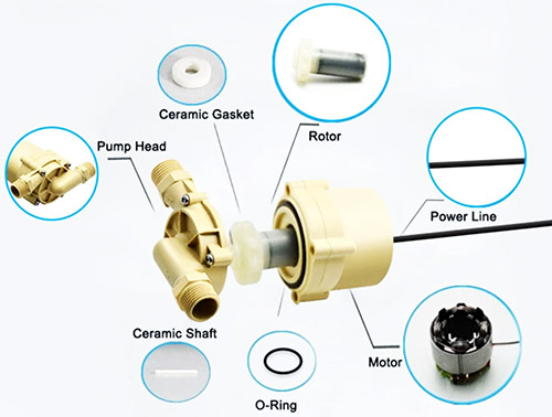
Motor Assembly
The motor assembly includes a high-purity enameled copper wire stator, high-coercivity NdFeB permanent magnet rotor and precision bearings. The stator adopts slotted winding design to reduce electromagnetic eddy current loss. The rotor uses high-temperature resistant permanent magnets to avoid demagnetization under long-term operation. Precision ceramic bearings or oil-impregnated sintered bearings are standard configurations, supporting low-friction long-term stable rotation.
Hydraulic Module
The hydraulic module includes corrosion-resistant engineering plastic or metal pump casing, precision injection-molded hydraulic impeller, standard inlet/outlet connectors and double-layer dynamic-static sealing components. It completely isolates liquid from the motor circuit to prevent leakage and short circuit.
Electronic Control Module
The electronic control module is a PCB integrated with BLDC dedicated driver chip, Hall sensor and full-protection circuit. It handles commutation control, speed regulation and fault protection, serving as the core for stable and reliable operation of the BLDC pump.
Types of BLDC Pumps
BLDC pumps and various specification BLDC water pumps are classified by hydraulic structure, installation method and performance grade. Each type has clear performance positioning, suitable for different industrial, civilian and new energy application scenarios.
Classified by Hydraulic Structure
Centrifugal BLDC pumps rely on impeller centrifugal force, with large flow, low head and smooth operation. They are widely used in liquid circulation and heat dissipation scenarios. Diaphragm BLDC pumps are driven by reciprocating diaphragm deformation, with small flow, high head and self-priming function, adapting to quantitative liquid transmission and high-pressure water supply.
Classified by Installation Method
In-line pipeline BLDC pumps are installed on horizontal pipelines, easy for installation and later maintenance. Submersible BLDC water pumps have IP68 high-grade waterproof performance and can work fully immersed in liquid, suitable for water tanks and underground liquid circulation. Side-mounted external BLDC pumps are fixed on equipment shells, saving internal installation space.
Classified by Performance Grade
Industrial-grade BLDC pumps have 20000+ hours of continuous operation life, with high temperature and pressure resistance. Consumer-grade BLDC pumps adopt cost-effective design, suitable for low-frequency operation household appliances.
Functions of a BLDC Pump
BLDC pumps have diversified practical functions based on basic liquid transmission. They fully meet the precision control, long-term operation and energy-saving demands of industrial and new energy equipment.
The core fluid transmission function can realize stable flow and pressure output under variable load. Flow control deviation is controlled within ±3% (according to industrial test standards), meeting the requirements of precision liquid circulation and pressurized water supply for every professional BLDC water pump.
The closed-loop stepless speed regulation function, cooperating with PWM or analog voltage signals, can flexibly adjust the impeller speed, change flow and head in real time, and avoid energy waste caused by full-speed operation.
The built-in overload self-protection function can automatically reduce power or cut off the power supply when locked-rotor, overcurrent, overvoltage or overheating occurs, preventing pump body burnout and protecting supporting electrical equipment.
The fully sealed structure achieves zero liquid leakage, avoiding medium pollution and circuit corrosion. The constant pressure/constant flow control function maintains the stability of the pipeline system, suitable for constant temperature cooling and quantitative liquid supply scenarios.
Key Advantages of BLDC Pumps
As we all know the BLDC pump is built by a brushless dc motor which make it with obvious irreplaceable performance advantages when compared with traditional brushed DC pumps. All advantages listed below are supported by actual industrial test data and on-site operation results.
Ultra-long Service Life
Without brush friction wear, bearing fatigue becomes the main aging factor. Continuous working life can reach 20000–60000 hours (industry standard test), 5 to 10 times longer than ordinary brushed water pumps.
High Energy Conversion Efficiency
Electromagnetic efficiency stays between 85%–95%. Under identical flow and head parameters, BLDC pumps and high-efficiency BLDC water pumps consume 30%–50% less electricity, delivering outstanding long-term energy-saving benefits.
Low Noise & Low EMI
No mechanical friction noise, running noise below 35dB (tested in semi-anechoic chamber). No spark interference during commutation, fully complying with strict EMC standards for precision electronics and medical devices.
Highly Responsive Speed Control
Millisecond-level dynamic response, speed fluctuation stays within 3% under changing water pressure and load. Good tolerance to frequent start-stop, high humidity and dusty environments.
Minimal Maintenance Workload
BLDC pump with no disposable consumable parts like carbon brushes. Only regular impurity cleaning is required, greatly cutting downstream maintenance cost and equipment downtime.
BLDC pump vs Brushed pump: What Is the Difference?
There are clear structural, operational and engineering differences between a BLDC pump and brushed pumps. These measurable performance gaps apply to every industrial BLDC water pump on the market.
1. Commutation Mode
Brushed pumps rely on physical brush and commutator contact, creating constant wear and electric sparks.While BLDC pumps use fully electronic non-contact commutation, zero wear and no electromagnetic interference
2. Service Lifespan
Brushed pumps only last 3000–5000 hours and need frequent brush replacement.While BLDC pumps can run stably for 20000–60000 hours with no consumable changes.
3. Energy Efficiency Rating
Brushed pump efficiency falls at 50%–65% with high friction loss. However, BLDC pumps reach 85%–95% energy utilization, far more cost-effective for long-hour operation.
4. Noise & Interference
Brushed pumps produce 50–65dB noise and strong EMI. But BLDC pumps can run quietly at 22–45dB and do not disrupt nearby sensors or control circuits.
5. Speed Stability
Brushed pumps show over 10% speed fluctuation under variable load. While BLDC closed-loop control can keep variation below 3%, supporting accurate hydraulic system adjustment.
BLDC Pump Flow & Head Test Methods
Test Preparation & Equipment
Before formal testing, prepare standard tools: electromagnetic flowmeter, pressure gauge (absolute pressure type), liquid storage tank, standard test pipeline, DC regulated power supply, tachometer and temperature sensor. Keep test medium (clean water) at 25±2℃, remove air in pipeline and BLDC water pump cavity, ensure all pipeline connections are sealed without leakage.
BLDC Pump Flow Test Method
- Connect the BLDC pump to the test pipeline system, fix the pump body, start the pump and run for 10 minutes to stabilize operating status.
- Install calibrated electromagnetic flowmeter on the horizontal section of the pump outlet pipeline, keep pipeline smooth without bending or blockage.
- Power the pump with rated voltage, record flow data shown by the flowmeter after 3 minutes of stable operation, take the average of 3 consecutive tests to reduce errors.
- For variable-speed BLDC pumps, test flow data under different PWM speed ratios and record the corresponding flow-speed curve.
BLDC Pump Head Test Method
- Install precision pressure gauges at pump inlet and outlet, keep test point distance within 1.5 times pipe diameter for accurate data.
- Run the pump under rated working conditions, record inlet pressure (P1) and outlet pressure (P2) at the same time, measure pipe diameter and liquid density.
- Calculate pump head using engineering formula:
H=(P2-P1)/ρg + (v2²-v1²)/2g + Z2-Z1
where ρ is liquid density, g is gravitational acceleration, v is liquid flow rate, Z is height difference between inlet and outlet.
- For standard BLDC water pump engineering tests, ignore velocity head and height difference under horizontal installation. Simplify to H=(P2-P1)/ρg, take average of multiple tests.
Test Notes
All tests follow industrial hydraulic test standards. Perform under rated voltage and non-overload conditions. Avoid bubbles, pipeline resistance and impurity blockage that affect results. Test data can be used for product performance verification and model selection reference.
BLDC pump Applications: Where Are They Used?
BLDC pump and BLDC water pump are widely used in scenarios that demand stable long-hour operation, low power consumption and precise fluid regulation. They cover new energy vehicles, industrial machinery, medical instruments and household smart appliances.
In EV thermal management systems, they support battery cooling, motor heat dissipation and vehicle coolant circulation, adapting to wide temperature ranges and continuous vehicle vibration.
Industrial applications include CNC machine cooling, server liquid cooling, laser constant-temperature circulation and large factory circulating water pipe networks.
Medical equipment uses miniature clean BLDC pumps for reagent delivery, dialysis liquid circulation and medical cooling instruments, meeting hygienic and low-interference operating requirements.
Household applications include floor heating circulation, instant water heater boosting, aquarium water flow and humidifier water supply, focusing on silent running and low energy use.
They are also widely used in photovoltaic energy storage, UAV auxiliary systems and automated robotic fluid circuits, becoming standard matching parts for modern intelligent equipment.
Power supply types for BLDC pumps
BLDC pumps support multiple mainstream DC power solutions: battery packs, adapters, industrial DC power supplies and off-grid photovoltaic systems. Different power input types directly affect stability, load tolerance, service life and applicable scenarios of a BLDC pump and customized BLDC water pump.
12V DC is the most common low-voltage type. It is widely used in automotive auxiliary systems, solar small circulation pumps, portable submersible pumps and household mini water equipment. It works well with lead-acid batteries, lithium batteries and standard DC charging adapters, safe and stable for daily low-power use.
24V DC dominates vehicle-mounted BLDC water pump, new energy battery cooling and medium-flow industrial circulating systems. Moderate voltage reduces line heat loss, supports stable heavy-load operation and adapts to large voltage fluctuation during vehicle battery charging and discharging.
48V high-power DC is designed for industrial large-flow, high-head BLDC pumps. Suitable for central circulating water systems, energy storage station thermal management and long-distance pipeline water transmission, greatly improving overall system energy efficiency.
In addition, high-grade BLDC pumps support wide-voltage fluctuating DC input, resisting unstable voltage from solar panels and battery discharge. Built-in voltage stabilization avoids speed drift, locked rotor damage and driver burnout caused by abnormal power input. Some custom models support automatic switching between mains DC and backup battery for uninterrupted fluid supply.
Why Industries Prefer BLDC pumps Over Brushed pumps?
Industrial production needs uninterrupted operation, low failure rate and long-term cost control. That’s why BLDC pumps and professional BLDC water pumps have become the undisputed mainstream replacement for traditional brushed pumps.
Most factory production lines run 24 hours non-stop. Brushed pumps suffer rapid carbon brush wear under continuous high-speed operation, requiring frequent shutdown maintenance and part changes that seriously hurt production efficiency. BLDC pumps have no wearing commutation parts and support full-day unattended stable operation.
Long-running circulating water systems create high electricity costs. High-efficiency BLDC pumps cut annual power consumption by 30%–50% (factory energy consumption records), bringing real cumulative energy-saving profits to enterprises.
Precision industrial automation systems are highly sensitive to electromagnetic signals. Spark interference from brushed pumps often causes sensor errors and program glitches. BLDC pumps output clean electromagnetic signals and ensure stable linkage of entire production lines.
BLDC pumps also perform better in humid, dusty and variable-temperature industrial environments. Lower failure rate reduces unexpected shutdown losses, matches automated precise flow control, and fully meets hydraulic matching needs of modern intelligent manufacturing.
Speed Control method
BLDC pumps use mature industrial speed adjustment technologies. Each method has unique advantages for different automatic control scenarios, fully compatible with all adjustable-speed BLDC water pump models.
PWM pulse width modulation control is the most common scheme. It adjusts average output voltage by changing signal duty ratio, achieving smooth stepless speed change with fast response and simple wiring. Suitable for most intelligent equipment and modular control systems.
Hall closed-loop feedback control monitors real-time rotor speed continuously. It automatically compensates speed deviation caused by water pressure changes and load fluctuations. Speed variation stays within 3%, ideal for constant flow and constant pressure hydraulic systems.
0–5V / 0–10V analog voltage control provides linear and stable speed adjustment. It easily connects with traditional PLC and analog control instruments without complex protocol debugging.
RS485 digital communication supports remote centralized control, multi-pump synchronous linkage, parameter modification and operating data upload. Widely used in large industrial circulating water stations.
Constant pressure closed-loop control automatically adjusts pump speed according to pipeline pressure feedback. It maintains stable system pressure and prevents pipeline damage caused by excessive water impact.
How to Choose the Right BLDC pump
Correct BLDC pump selection uses systematic engineering calculation, not blind parameter picking. The logic covers 5 core dimensions and applies to every standard BLDC water pump on the market.
First, confirm matching rated voltage: 12V, 24V, 48V, to avoid driver burnout or unstable speed from voltage mismatch.
Second, calculate accurate hydraulic parameters. Measure pipeline length, height difference and bending resistance. Select flow and head with 10%–15% safety margin (engineering best practice) to ensure stable water output.
Third, distinguish conveyed liquid properties. Use corrosion-resistant models for special media, high-temperature models for hot water, food-grade materials for drinking water and medical fluids.
Fourth, confirm installation type and protection level. Choose submersible, inline or external pumps based on space, select IP54 to IP68 sealing grade according to humidity and dust level.
Fifth, clarify control requirements. Use fixed-speed pumps for simple circulation, PWM or RS485 adjustable-speed pumps for automatic precision systems. Always prioritize products with full overload, overheating and locked-rotor protection functions.
How to Use BLDC Pump & Operation Precautions
Standard Usage Steps of BLDC Pump
Step 1: Pre-Installation Inspection
Check the BLDC pump and BLDC water pump for appearance damage. Confirm rated voltage, power, flow and head match application requirements. Check whether the internal impeller spins freely without jamming or abnormal noise. Clean inlet and outlet to remove packaging impurities.
Step 2: Correct Installation
Install the pump horizontally or vertically according to the product manual. Ensure pipeline is coaxial with pump interface to avoid mechanical stress. Seal all pipeline connections tightly to prevent air intake or liquid leakage. For submersible BLDC water pumps, ensure the entire pump body is immersed in liquid and the cable is properly sealed and fixed.
Step 3: Wiring & Power Connection
Connect power cord strictly according to the wiring diagram. Match rated voltage (12V/24V/48V) accurately, avoid reverse positive and negative connection. Ground industrial pump body reliably for electric leakage protection. Do not use unqualified voltage regulators or power supplies to avoid driver damage.
Step 4: Pre-Operation Debugging
Fill liquid into pump cavity and pipeline to remove internal air. Never run dry. Power on for short-time commissioning, check rotation direction, operating noise and vibration. Adjust speed control module (if equipped) to test flow and head change stability.
Step 5: Formal Operation
Start the pump under rated working conditions, monitor operating status in real time. Record operating voltage, current, temperature and liquid flow data regularly. For long-term continuous operation, keep the working environment well ventilated and the medium clean.
Step 6: Shutdown & Storage
Turn off power supply before stopping the pump. Close pipeline valves if needed. Drain internal liquid completely if the pump is idle for a long time, store in dry, ventilated and non-corrosive environment, conduct regular inspection every 3 months.
Non-Negotiable Operation Precautions
- Dry Running Prohibition:
Strictly forbid dry running of BLDC pump without liquid. Maximum allowable dry running time shall not exceed 3 minutes (factory test data). Otherwise, sealing ring and bearing will burn out instantly.
- Voltage Control:
Operate strictly under rated voltage. Voltage fluctuation range shall not exceed ±10% of rated value. Overvoltage or undervoltage burns drive circuit and motor winding.
- Medium Limitation:
Standard models only allow clean water, weak coolant and non-corrosive liquid. Do not deliver granular impurities, strong acid, alkali or oily medium to avoid impeller wear and pipeline blockage.
- Overload Avoidance:
Do not run the pump under long-term overload such as excessive head, blocked pipeline or overpressure, which causes overheating and damage.
- Environmental Requirements:
Keep pump drive module away from water, humidity, high temperature and strong electromagnetic interference to prevent circuit short circuit and signal disorder.
- Maintenance Taboo:
Do not disassemble pump body and drive module without professional guidance, to avoid damaging internal precision parts and waterproof structure.
- Start-Stop Management:
Avoid frequent violent start-stop in short time, which causes current shock and shortens service life of motor and driver.
Maintenance and Troubleshooting Tips
Standard daily maintenance effectively extends service life of BLDC pumps and BLDC water pumps. Targeted troubleshooting quickly fixes common faults without professional disassembly.
Daily maintenance:Install fine filters at water inlets to block sand and debris.Tighten pipeline connectors regularly.Never run dry.Keep drive boards away from moisture and high temperature.
Common fault solutions:Insufficient flow and low head usually come from filter clogging, trapped air inside pump or low input voltage. Clean impurities, exhaust air and check power supply stability.
Abnormal noise is caused by foreign matter on impellers, loose bearings or unstable pump fixation. Clean rotating parts and install the pump firmly.
Failure to start relates to reverse wiring, poor contact or rotor locking. Correct circuit connection and remove blocking objects immediately.
Pump overheating is caused by pipeline blockage or long overload. Stop operation temporarily for cooling and clear fluid channels.Shaft leakage requires timely replacement of aging sealing rings.Complex circuit faults must be handled by professional technicians.
Frequently Asked Questions
Q: What temperature range do industrial BLDC pumps support?
A: Standard industrial BLDC pump models work stably from -20℃ to 80℃. Custom high-temperature versions can withstand up to 120℃ to avoid permanent magnet demagnetization (material test data).
Q: Is dry running acceptable for BLDC pumps?
A: Prolonged dry operation damages shaft seals and bearings. Safe dry running time is limited to no more than 3 minutes, also applicable to sealed BLDC water pump units.
Q: What’s the difference between 120° and 60° Hall commutation?
A: 120° commutation delivers low torque ripple and smooth running. 60° commutation provides higher control precision, used in high-speed BLDC pumps.
Q: Can BLDC pumps be connected in series or parallel?
A: Parallel connection increases total flow. Series connection improves overall head. Only same-parameter BLDC water pumps should be matched to avoid backflow.
Q: How to prevent permanent magnet demagnetization?
A: Avoid long overcurrent, overload and ultra-high temperature operation, use high-coercivity NdFeB magnetic materials (industry standard).
Q: Do BLDC pumps need external independent drivers?
A: Integrated BLDC pumps have built-in drivers. Separated motor-type pumps require matched special BLDC driver controllers.
For detailed installation, operation, daily maintenance and troubleshooting solutions of brushless DC pumps, you can refer to our Brushless DC Pump Ultimate Guide
Summary: Why BLDC pumps Are the Industry Standard
After years of global market verification and continuous technical iteration, BLDC pumps and high-performance BLDC water pumps have become universal industry-standard DC fluid transmission components, leading the full upgrade of the global pump equipment industry.
The BLDC pump structure fundamentally fixes the inherent flaws of brushed pumps: short lifespan, high energy waste, loud noise, serious electromagnetic interference and frequent maintenance needs. It perfectly meets the core demands of new energy vehicles, intelligent manufacturing and automated equipment for long, stable and high-efficiency continuous operation.
With outstanding energy saving, precise controllability, strong environmental adaptability and low overall operating cost, BLDC pumps have formed mature global technical specifications and a complete application ecosystem.
Driven by global energy-saving policies and industrial intelligent upgrading, BLDC pumps will further replace traditional hydraulic equipment. Their stable performance, wide compatibility and reliable quality determine their long-term leading position in the global DC fluid transmission market.